Table of Contents
AVR programmer for begginers
This project is for educational purposes only.
I AM NOT RESPONSIBLE FOR ANY INJURY OR DAMAGE CAUSED BY USE OF THIS INFORMATION.
Currently popular programmers have the following disadvantages:
- Relatively expensive
- Complicated - Presented programmer requires minimum amount with functionality tradeoff.
- Require another programmer to start working!
The code is based on project that is a part of LUFA framework (Lightweight USB Framework for AVRs by Dean Camera): http://www.fourwalledcubicle.com/AVRISP.php. The board is my design.
Programmer advantages
- Thanks to build-in USB bootloader another programmer is not required to get the device running.
- Allows powering target device.
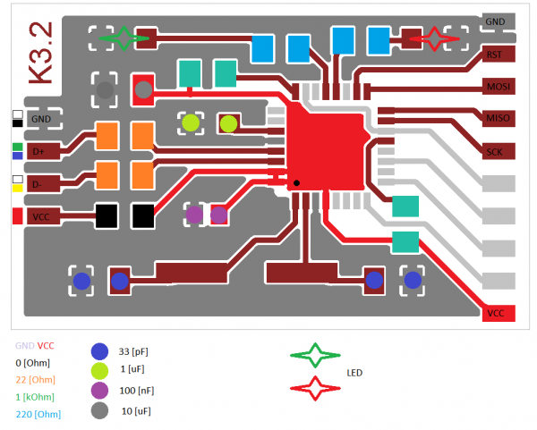
- All parts are in SMT technology, therefore PCB does not require drilling
- Only 5 elements require special attention to package direction (harder to make mistake)
- Works with AVR Studio or AVRDUDE (selectable by firmware)
- Low cost
- Small
- 4 [MHz] rescue clock output
- ISP, PDI and TPI programming interfaces
- True USB (unlike USBASP)
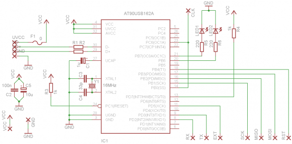
Schematics
BOM
| Element | Wartość | Opis |
|---|---|---|
| IC1 | AT90USB162 | microcontroller |
| USB | - | solder field for USB wire |
| F1 | 500 [mA] | Polymer fuse |
| R1 R2 | 22 [Ω] | USB-line impedance-match resistors |
| C1 | 1 [uF] | 3V3 USB voltage stabiliser capacitor 1) |
| C3 C4 | 33 [pF] | oscillator capacitors |
| Y1 | 16 [MHz] | quartz oscillator |
| C2 | 100 [nF] | power bus decoupling capacitor |
| C5 | 10 [uF] | power bus decoupling capacitor |
| R3 | 1 [kΩ] | pull resistor |
| R4 | 1 [kΩ] | bootloader line pullup resistor |
| R5 R6 | 1k ÷ 220 [Ω] | LED resistors |
| LED1 LED2 | Signal LEDs | |
| Goldpin headers |
Launching
- Check all components and connections
Software
1. Download required tools:
- Most recent LUFA release (requires modification)
- Atmel FLIP (windows) or DFU-programmer (Linux)
- (Extra) USBView
Linux users should download appropriate tools and use them accordingly to their OS.
Code from LUFA requires modification: pin PB4 must be inactive (high impedance mode). To reduce board layer count one trace crosses one pin. Pin is unused in this application and must remain floating. Therefore user must modify IOs initialization code.
2. Connect device to the PC. You should see a new device using Device Manager or USBView. Linux users can use lsusb
3. Install DFU drivers from Atmel FLIP directory. (Linux users should follow instructions for DFU programmer).
4. If user compiled the firmware on his own, he can use a make script to program the device. If user use precompiled code:
- Run Atmel FLIP
- Select Device→Select…→AT90USB162→OK
- Select Settings→Communication→USB
- When window USB Port Connection opens choose Open
- Select File→Load HEX File… and open appropriate file
- In the Operations Flow tab click Run
- Close Atmel FLIP
5. Reset programmer trough re-plugging it from PC USB port. Among USB devices user should see a new device. Drivers for it are located in the libUSB-win directory.
6. If our system does not accept unsigned driver user need to generate appropriate INF file using inf-wizard application from libUSB-win directory.
If you have AVRStudio installed your system most likely has Jungo WinDriver drivers installed. This programmer will not work with those drivers, you need to force using libUSB drivers.
How to use programmer
If you use AVRDude please use following scheme:
avrdude -pXX -cavrispmkii -P usb
where XX put target device name (ex. -pm8 for ATmega8). Useful argument is
-B 4
that sets the period of clock signal (in this case 4 [us] → 250 [kHz])
Firmware upgrade
MCU manufacturer uploads bootloader to the chip during fabrication process. Bootloader code is located at the end of program memory. After reset PC (program counter) is “jumping” over NOP-filled (NO Operation) memory till it reaches the bootloader code. After firmware upload bootloader does not start automatically. We can force MCU to jump directly into bootloader code after reset. To do so:
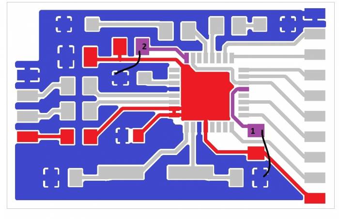
- Pull-down HWB (HardWare Boot) line to the ground [1]
- Reset MCU trough pulling reset line to the ground. [2] (HWB must be pulled down during reset!)
Schematic below shows point you should short (programmer must be connected to the PC during the process).
Metal tool such as callipers can be used. One of the signals can be pulled using GND wire from the programmer pin header.
Take attention to the procedure. Accidental shorting of power line to the ground might influence your PC. I have marked the power line by red, ground plane by colour blue and signal lines to be pulled-down by violet.
Files
- programmer_v3.zip Schematics (Cadsoft Eagle 6)
- MCU code Maj 2012


